The TAG-8600 Wireless High Voltage Nuclear Phase Meter independently developed by our company is suitable for the 5V-220kV voltage range core phase. Among them, the 10kV line nuclear phase application is the most widely used. The following describes several nuclear phase methods for the 10kV line.
1, 10kV overhead line nuclear phase
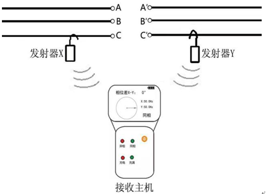
The nuclear phase of the 10 kV overhead line belongs to the high-pressure nuclear phase. The nuclear phase method is shown in the figure. The X and Y emitters are respectively hung on the desired phase of the nuclear phase through the insulation rods. The receiver will then broadcast the nuclear phase results in voice and display the phase difference and vector diagram.
2, 10kV cable line phase
Because the 10kV line is mostly a three-phase cable line, the three-phase cable can only perform the nuclear phase at the switch cabinets at both ends of the cable. There are two commonly used nuclear phase locations, one is the cable entry T-junction, and the other is the switch. Charged display on the cabinet.
The T-junction at the nuclear phase belongs to the high-pressure nuclear phase. The nuclear phase method is shown in the figure. When the nuclear phase is taken into account, the emitter must be in contact with one phase and away from other phases as far as possible to avoid excessive distance signal interference. This nuclear phase method needs to open the cable compartment door of the switchgear. Some five strict switchgear cabinets are not allowed to open the cable compartment door under live conditions. At this time, it is necessary to check the phase on the live display.
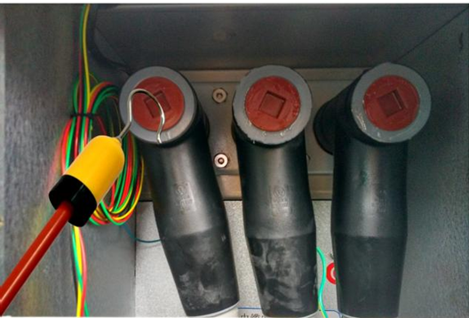
The charged display core phase belongs to the low-voltage nuclear phase. The yellow, green and red terminals of the live display are in one-to-one correspondence with the yellow, green and red three-phase phases of the busbars and cables of the switchgear. The nuclear phase method is shown in the figure and will be launched. The hook terminal of the device is replaced with a pre-proportioned tip terminal, which is directly inserted into the charging hole. At the same time, the ground terminal of the transmitter (which is also the charging hole) is grounded through a dedicated grounding wire to be nuclear phase.
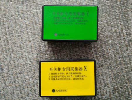
If the switchgear neither has a live display nor can it open the cable compartment door with electricity, you need to configure the central cabinet collector to power off the switchgear first and then tie the X and Y collectors to the required phase. Busbars or handcart busbars can be measured when powered on again.
High Power Graphite Electrode
Use and performance of Graphite electrodes
use
Used in steelmaking electric arc furnace, refining furnace, as conductive electrode; Used for industrial silicon furnace, phosphorus furnace and corundum furnace, as conductive electrode.
performance
High resistance to thermal shock and high mechanical strength
grade
High power Graphite Electrode (SHP) high power graphite electrode (UHP) with high power graphite electrode (HP) with high power graphite electrode (R
Precautions for use of graphite electrodes
1. According to the capacity of the electric furnace and the load of transformer, the grade and diameter of the electrode are suitable
2. When loading the electric furnace, the bulk charge shall be placed in the bottom of the furnace so as not to break the electrode. In the process of smelting, the lime should not be conductive. Large masses of objects are concentrated directly below the electrode, otherwise it will affect the electrode and even cause the electrode to break.
3. Attention should be paid to the position of the furnace cover. If the furnace cover is offset, the cover of the furnace will be blown on the lifting electrode, causing the electrode to be damaged.
4. When connecting the electrode, if the defect of joint bolt is found, the connection should be made after replacement
5. After the electrodes are connected, if there is a gap in the connection surface, it is important to find out the reason
6. The electrode should be used vertically.
7. The electrode holder shall be sandwiched between the upper and lower levels of the top electrode, and shall not be sandwiched between the warning line and the middle electrode. Otherwise, the electrode column is easily broken
8. The raw materials and production techniques of different manufacturers may vary. The physical and chemical properties of the electrode are also different, and it is recommended that the joints and electrodes produced by different manufacturers should not be used in a different way.